Signal Reader Assignment Editor
The Signal Reader Assignment Editor, also known as haf creator, can be found under the tab Assignment and allows the user to create new assignments for signal reader directly on the portal. This page will guide you through the basics of using the editor.
Edit/Create a signal reader assignment
The first tab that you are presented with is the Assignment global settings tab where you can add information about the assignment so that you can easily keep track of what this assignment is about. Creator and creation date are both automatically filled in and cannot be changed because of consistency.
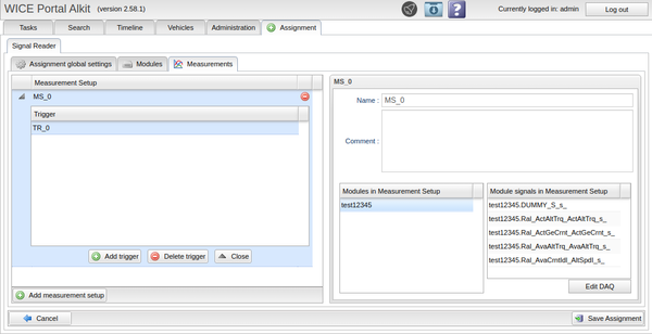
Under the Measurements tab, see Figure "Measurement Setups", you are presented to a table of Measurement Setups and an information window. These measurement setups are the core of a signal reader assignment. They contain Triggers that activate and deactivate on certain conditions provided by the user. Each trigger can contain a Recorder that contains a list of certain signals that will be measured when the start condition for the respective trigger is met. A trigger can also be used to act as a setup switch.
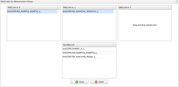
Measurement setups keep track of the signals that are present in them, as seen in Figure "Measurement Setups". If a CCP signal is present in the measurement setup it is possible to assign it to an individual DAQ list by pressing Edit DAQ. This brings up the window in Figure "Edit DAQ". Here you can drag and drop signals to the corresponding DAQ list that you which them to be in.
When you feel finished with the assignment you can simply click the Save assignment button in the lower right corner to save the assignment in its current state.
Trigger
To add a trigger to a measurement setup, click the Add trigger button for the respective measurement setup. This will create a new Trigger in the trigger table in the respective measurement setup and the information window will be filled with new settings for this trigger for you to add.
Fill out the start trigger condition for the trigger. This is easiest to do in the Edit expression window that you can get to by clicking one of the Edit buttons. To find a new signal to add a condition for, use the Add signal button. Here, you can browse all signals available for this assignment. Use the dropdown to browse signals from different can-busses and Wice generic internal signals. If you want to browse the signals currently in use in the assignment for the selected signal source, check the Search in assignment box. If you want more information about a signal, select it and click More info. When you have found the signal you want, double click it or select it and click Add signal. Now you can use the Operators list to add a condition for the signal, for example " > 0". When you are satisfied with the start condition, you will notice that the Validate button has a yellow warning symbol on it. This means that the expression is unvalidated, press the button to validate the expression. The buttons icon now either turns red (expression is unvalid) or green (expression is correct). See Figure "Validate Button States" for the different state of the validate button. Click Save to save the expression. The list of operators supported in trigger condition is available here.
A stop trigger condition is not required, but can be supplied to determine when the recording should stop. If the stop condition is not supplied, the settings for the recorder will tell when the recording should stop.
You can use the trigger Setup switch to switch to/run a measurement setup when the start condition is met. Keep in mind though, that the setup switch will not run until all currently started recorders have at least fulfilled their minimum duration. A trigger with a recorder cannot have a setup switch, but the recorder can.
Recorder
There a two types of recorder, SREC (Signal recorder) and DREC (Diagnostics recorder). Choose which one you want with the radio button at the top of the Recorder tab.
Recorder - DREC
DREC (Diagnostics recorder) is used to send diagnostic requests onto the vehicle's communication buses and record the responses. The diagnostic requests are supplied in a sequence file uploaded by the user. The sequence file contains one diagnostic request per line, with the ECU id at the beginning of the line. There can optionally be other information as well. The syntax is the same as the one used for the IDC module, see Sequence File Syntax. The result from a DREC will be a diagnostic log file, a text file containing both the requests from the sequence file and the corresponding responses.
Recorder - SREC
SREC (Signal recorder) is used to record signals on the vehicle's communication buses. The result of an SREC is an MDF file containing the time series data of the selected signals.
SREC - Signals
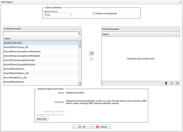
Click the Add Signal button to open a window to add signals for recording. This window is much like the window for adding signals for the trigger, only differing in the fact that you can select multiple signals in this window. The selected signals for this recorder are shown in the right table, see Figure "Add Signals for Recorder". To add new signals to this table, you can either:
- Double click the signal,
- Drag and drop the signal
- Select the signal and click the right pointing arrow
Click the red symbol to the right of each signal to remove it. When you are done, click Ok to add the signals.
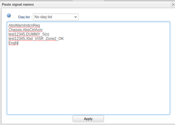
It is also possible to import signals from a text file or directly from text as well as export signals as text. To do this, use the corresponding icon in the bottom right corner of the "Selected Symbols" list as senn in Figure "Add Signals for Recorder". The figure "Import signals from text" gives an example on how the text file and text is expected to be structured when importing signals. Each line is expected to be a signal, with or without the module name. If the signal does not have a module name it is expected to belong to the already selected signal source/module. When importing CCP signals it is here possible to select which DAQ list that all found CCP signals should be assigned to, using the drop down.
Now that you have added some signals, you can give them each a Skip factor, default 1, which is an integer that determines how often the signal should be recorded/stored when supplied. For example, a skip factor of 1 will record the signal every time it is supplied and a skip factor of 3 will record the signal every third sample.
PLA-Compressions level can be set per signal by clicking on the pla column for the signal or select a row and click on “Edit PLA”. Read more here.
Recorder - Properties
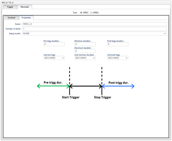
Under the recorder tab Properties you can select the properties for the recorder, see Figure "Recorder Properties".
Number of shots is an important factor for a recorder. A shot is the term used for a single recording and number of shots is therefore the number of times we should record. A shot is only started when the start trigger condition is met and will continue until any of these events occur:
- The recording fulfills the maximum duration.
- The recording fulfills the minimum duration and the stop trigger condition is met.
- The recording fulfills the minimum duration and a trigger start a setup switch.
- The recording fulfills the minimum duration and another recorder starts a setup switch.
- A setup switch is started manually.
- The assignment is stopped manually.
The recorder Setup switch is started when recorder has performed its number of shots and all other started recorders have at least fulfilled their minimum duration. It is, like the trigger setup switch, used to switch to/run a measurement setup.
You can also select the Pre trigg duration which determines the amount of data that will be saved in the flash before the start trigger condition is met. Range is 0 to 4294967295 (232).
The Post trigg duration is much like the pre trigg duration and determines the amount of data that will be saved after the stop trigger condition is met. Range is 0 to 4294967295 (232).
The Minimum duration determines the minimum amount of data that needs to be recorded before it becomes possible to cancel the recording through either a stop trigger or a setup swtich started by a trigger or another recorder.
The Maximum duration determines, as the name suggest, the maximum amount of data that should be recorded. Range is 0 to 4294967295 (232).
The Unit for the four aforementioned durations can be set to seconds, samples or bytes. If you choose to set them to seconds, the device will use the timestamps of the incoming data to determine the four aforementioned durations.
Active signals
An Active Signal is a signal that is created by polling an ECU for a numerical value at a predefined frequency. The polling is typically done using the ReadDataByIdentifier diagnostic service. To create an assignment with active signals, the vehicle profile has to have a diagnostic description. This is set in the vehicle profile settings here. There has to be a diagnostic description connected to the vehicle profile when the assignments are created to be able to select active signals. If a vehicle profile is updated, an assignment can be upgraded to match the new vehicle profile by doing a copy. This will automatically upgrade it and if there is a diagnostic description connected it will be possible to use active signals.
Select “Active signal” in signal Source. Then it is possible to select ECU in ECU name. After that available signals will show up and select/deselect works like for the other signal sources.
When creating a task with an assignment that has active signals selected, a button “ECU SW mappings” will show up. If there is a red exclamation mark, a specific software version has to be selected for one or more ECUs. If a recorder signal does not exist in the selected software version it will be removed. Note that the software version has to contain all active signals that exist in the trigger conditions otherwise it will not be possible to create the task.
Using a portal assignment for a signal reader task
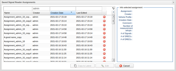
In order to use a portal assignment. Select the WCUs in the Vehicle tab that you want to create the new signal reader assignment for and click new task. Navigate to the Signal reader tab and click the Browse saved assignments button and select the assignment you want to use and click Ok. This assignment will now be used to create the .haf file required by the WCUs to perform the signal reader task.
Select different communication interface or transport protocol
Under the "Modules" tab, the different signal sources are visible. In the "I/O" column, the selected communication interface and transport protocol are shown. By selecting a row and then clicking on the button “Edit Interface” this can be changed. Currently this is only possible for modules with type “A2L” or "Diagnostics." When changing this, a validation of the settings with what is red from the corresponding A2L file is done. If the validation is successful, a green icon will appear. If the icon is a red cross the A2L file does not contain the necessary information for the setting.
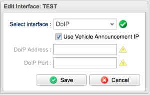
When selecting between CAN and Ethernet/DoIP diagnostics, a window pops up where you can select the interface between "Default Channel", "CAN" or "DoIP". Selecting "Default Channel" means that the default channel in the signal reader module settings on the wcu is going to be used. Interface "CAN" a specific CAN interface can be selected to be used for the diagnostic requests. If selecting "DoIP", the diagnostics will be performed over Ethernet using the Diagnostics-over-IP (DoIP) protocol. In this case, you can also select whether to use the IP address broadcasted by the vehicle in a "Vehicle Announcement" message, or you can specify the IP address explicitly (in which case the Vehicle Announcement will be ignored). The DoIP port number to use (default 13400) can also be specified.
A2L modules support the following interfaces, CPP-CAN, XCP-CAN, XCP-TCP, XCP-UDP and UDS (2C/2A).
Record frames with filter
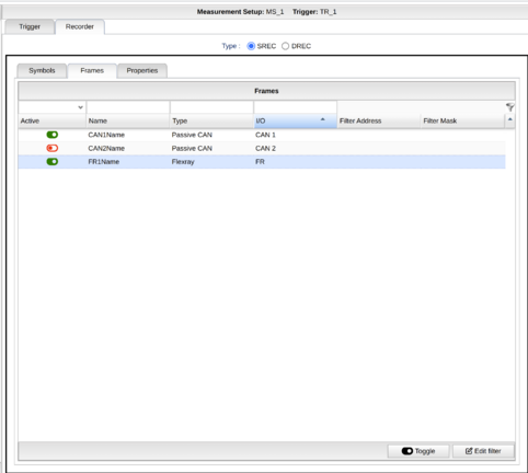
Frame recorder can be used on FlexRay and CAN-bus. In a signal recorder the frame recorder with or without filter can be activated.
To activate/deactivate the frame recorder for a module either click on the active icon or select a specific row and click Toggle.
To edit the filter either double click on row or click on edit filter.
