Difference between revisions of "Creating a Task"
Robin.karhu (talk | contribs) |
Robin.karhu (talk | contribs) |
||
| Line 58: | Line 58: | ||
[[File:Illustration Schedule.png|thumb|left|600px|Schedule Panel]] | [[File:Illustration Schedule.png|thumb|left|600px|Schedule Panel]] | ||
[[File:Scheduling on ignition.png|thumb|300x300px|Schedule Panel with 'On ignition' enabled]] | |||
<br clear="all"> | <br clear="all"> | ||
Revision as of 10:58, 25 November 2022
You create a new task by pressing the "New Task" button on the bottom of the "Tasks" tab. This will open a window where you choose the type of task you want to create. Note that it is not possible to create a new task for a WCU which has the system labels ''shelving_in_progress'' or ''shelving_done''. However, if the WCU has the latter label, it is possible to unshelve it using the corresponding button in the bottom of the Vehicle-tab. Here we will go through how to create tasks of each of the different kinds of tasks available. Remember that not all of the task types will be available as this depends on customer configuration and some types might not be enabled in the portal.
To learn about how to add resources to the task, check here.
Arcos
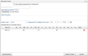
The WICE system can interact with external loggers as well. From version 2.71 the portal can interact with the Arcos-logger from Ipetronik. You create your measure task using an external tool which creates a file which you can upload for this type of task. The file should have the extension ".ccmc". When the task is downloaded the WICE system will then forward this file to the external logger. The WICE system can also take care of uploading the result files as well where you can retrieve the files using this portal.
Select the "Use existing measurement configuration" checkbox if a measurement setup file already exists on the Arcos - no upload will be required.
Area5
Area5 tasks are used to read out data from the memory of ECUs.
Assignment: To create a new Area5 task you first have to create an Area5 assignment in the Area5 Assignment Editor.
Validate ECU SW version on WCU: By checking this box, the WCU will validate that the ECU SW version of the task and the actual ECU are the same before starting the task. If they are different, it will not start the task.
Trigger Expression: The task can be started by an expression. This option lets the user specify start trigger conditions based on logical expressions containing signals measured by the Signal Reader module. Note that the user must make sure the signals present in the expression are actually measured (otherwise the expression will never be true). For an explanation of trigger conditions look here.
Sync Signal: It is possible to specify a signal with given values that will be sent when the Area5 task starts and stops. This can be used to synchronize the Area5 read-out with external measurements systems like the M-Log.
Audio
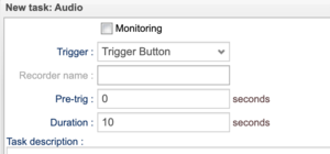
An audio task makes it possible to record audio from a connected microphone. An audio recording can be started in five ways:
- Trigger button: to initiate the recording you need to attach a button to the WCU in order to start in the audio recording.
- Signal reader: initiate the recording by a trigger expression in a Signal Reader assignment. The recording is started as soon as a Signal Reader recorder is started. You specify the name of the Signal Reader recorder (e.g. SREC_0) you want to start the audio recording. You can also enter "auto" as the recorder name, in which case a recorder that include the Audio_Device_n internal signal will be selected.
- Expression: Similar to the 'Signal reader' trigger option, the 'Expression' option lets the user specify start and stop trigger conditions based on logical expressions containing signals measured by the Signal Reader module. Note that the user must make sure the signals present in the expression are actually measured (otherwise the expression will never be true). Unlike the 'Signal Reader' trigger, there does not have to be a recorder configured in the Signal Reader measurement assignment. For an explanation of triggers look here.
- Audio level: Start the trigger once the microphone registers volume above a certain threshold.
- None: start the recording as soon as possible.
In addition to this, you can set the pre-trig time which is only valid in the cases of trigger button, signal reader, expression and audio level above. As an example, let's assume the trigger button method is selected. At the moment the trigger button is pressed the audio has already been recorded for the number of seconds specified. This can be handy when you press the trigger button to make a comment about an event where the event was audible.
A maximum duration of the recording can also be set, in seconds from the start trigger event. If there is a stop trigger expression specified, the recording will be stopped either when the stop expression is fulfilled or the max duration is passed, whichever occurs first. If you do not enter a duration it will be set to a default value of 120 seconds.
It is possible to monitor the audio live. To do this, check the box "Monitoring". To listen to the live audio you should use a tool such as Alkit Confero.
There is more information about audio in WICE here.
Audio tasks can be scheduled in the same manner as described for the Canrecoder task.
Blue piraT
The blue PiraT is a measurement system from Telemotive AG that can be configured with measurement set-ups, and data accessed through the WICE Portal. Note that to use the blue PiraT module, the WCUs to be used need to be preconfigured with a special software package (i.e. an "extra bundle"). Contact Alkit Communications in order to set this up.
CAN-recorder
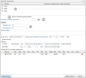
Canrecorder is a measurement module that allows CAN frames to be captured and logged. This task has four options described in Figure "Canrecorder" and below:
1. In the grid, select which bus (or buses) to record from. By clicking the check box in the top left corner, you can select all buses at once.
2. Specify which CAN frames you want to record by entering their CAN IDs in the CAN frame ID column in the grid, on the same row as the bus you have selected, or by entering the IDs in the text box labeled “Set filters on selected CAN buses”. If you use the latter option, the filters will be set on all of the buses you have selected. To enter a filter on a specific bus use the method of entering the filter on the same row as the selected bus, on the grid. This can only be done if the CAN frame passthrough filter is turned on. Turning off the CAN frame passthrough filter option will disable the CAN frame ID column in the grid. Press the “Clear All” button to remove all the entered filters from all buses.
3. Turning on or off a CAN frame pass-through filter. If you choose to have the filter on you must specify which CAN bus or CAN buses you wish to record.
4. Select how long time to record before and after the trigger.
Scheduling
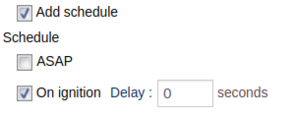
For WCUs with version >= 2.53 this task can be scheduled by selecting the "Add schedule"-checkbox. By doing so, the panel shown in Figure "Schedule Panel" appears. By thereafter selecting the "ASAP" checkbox, the task will be performed once and as soon as possible. If instead the task is to be performed at a specified time, deselect the "Time span" and "Repeat"-checkboxes and select the sought time in the "Start field". The task can also be performed within a certain time span, and in this case "Time span" should be checked and the Date in "End" field specified. Repetition of the task is defined by checking the "Repeat" checkbox, defining a interval size in the field after "Every" and a recurrence rate in the drop down menu. The task will then be repeated at this rate until the date defined in the "Until" field is reached. By selecting the "On ignition" checkbox, the task will be performed once on ignition. If delay is above 0 then the task will be performed once the configured amount of seconds have passed after ignition.
To control the time zone in which the task scheduling is to be performed the "WCU local time"-checkbox is used. If this option is deselected, the task will be performed in UTC-time (the date fields present the portal local time). On the other hand, if this box is checked, the task will be performed according to the local time zone predefined for the WCU. A WCU time zone can be defined for a WCU with version >= 2.53 by an administrator using "Edit configuration" in the Vehicles panel. This is useful when there is a need to perform a certain task at a specific time of the day regardless of which country the vehicle is in. For instance, when selecting 100 different WCUs scheduled to perform a task at 10:00, checking the "WCU local time"-checkbox will result in them performing the task according to their time zone setting. Without checking this option, the task will be performed in the corresponding UTC-time, which could mean in the middle of the day or night depending on where the vehicle is located.
Diagnostic Log and Trace (DLT)
DLT itself provides a log and trace interface, based on the standardised protocol specified in the AUTOSAR standard 4.0 DLT. A DLT task in the WICE Portal makes it possible to collect such logs in a vehicle where this functionality is available and transfer the data to the WICE portal where logs can be downloaded for further analysis. For a more in-depth description, you can go here.
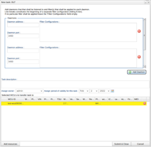
Basically the WCU is connecting to one or more DLT Daemons and unique filters can be applied to each daemon, filtering out specific log messages.
So when creating a DLT task on WCUs with software version 2.72.0 or later the number of daemons can be specified and for each daemon the following needs to be specified:
- Daemon address - the IP-address in order for the WCUs DLT client to find the daemon.
- Daemon port - which port on the address the daemon is at.
- Filter configurations - filter expressions to be applied on the log messages. If left empty no filter is applied. For an explanation on how to write filter expressions, see here.
Older WCUs
For WCUs with software version earlier than 2.72.0 only one daemon is supported and only filters can be configured when creating a DLT task. To specify the daemon address and port go to the DLT Module instead.
ETAS
Through an ETAS task, an ETAS ES720 Drive Recorder system can be configured, and measurement data offloaded and accessed through the WICE Portal.
When creating an ETAS task, the task description file you select must be a .exp file.
Ethernet capture
This kind of task is used to capture packet data from one of the ethernet interfaces on the WCU. The basics for this kind of task is that you choose the interface you would like to capture from and a capture expression to filter which packets you are interested in. The results from this task type is pcap files. To read more about this task type, go here.
File fetcher
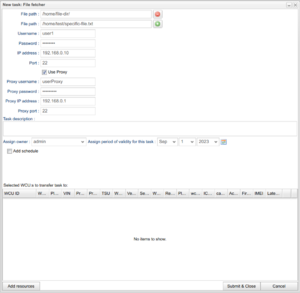
The File fetcher task fetches files from a specified unit and makes them available for downloading in the Portal.
The following needs to be specified when creating such a task:
- File path - One or several paths to a files or file-containing directories on the unit's file system. This specifies which files that will be fetched.
- Username - To log in to the unit.
- Password - To log in to the unit.
- IP address - To find the unit.
- Port - To find the unit. Default is 22, but can be changed.
Furthermore, the task also allows the use of a proxy.
To use a proxy, the Use Proxy checkbox has to be checked, and the following must be specified:
- Proxy Username - To log in to the proxy unit.
- Proxy Password - To log in to the proxy unit.
- Proxy IP Address - To find the proxy unit.
- Proxy Port - To find the proxy unit. Default is 22, but can be changed.
IDC
The Internal Diagnostic Client (IDC) is a measurement module that allows a sequence of diagnostic requests to be sent and responses recorded. The sequence of diagnostic requests are uploaded to the portal as a text file (usually ending with ".seq"). This task can also be scheduled in the same manner as described for the Canrecoder task.
M-Log
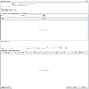
The WICE system can interact with external loggers as well. One such logger is called M-Log from Ipetronik. You create your measure task using an external tool which creates a file which you can upload for this type of task. The WICE system will then forward this file to the external logger. The WICE system can also take care of uploading the result files as well where you can retrieve the files using this portal.
Select the "Use existing measurement configuration" checkbox if a measurement setup file already exists on the MLOG - no upload will be required.
Available from version 2.74.0
The measurement assignment for an MLOG is created using an external tool to WICE. An assignment is created with a certain version of the ECU software in mind for each ECU in the assignment. In order for the assignment to work it might be important that the ECU software version in the vehicle matches the software version of the ECU it was created for. In WICE, you can ask the system to read the current software version for each ECU which is stored and can be viewed, e.g. via the ECU list. As WICE cannot know which software versions the assignment was created for, the user can supply this to WICE. By doing that, WICE can validate the entered software versions against what has been read out for each vehicle and thus aid the user in making sure that an assignment will work once it will run.
To make the validation possible the user enters a ECU by its address, not the name. To help find out the address for an ECU you can go to the ECU list to find the address of a specific ECU. Have a look at the illustration, Entering ECU software version, to see where in the dialog this is entered. On the top you enter the ECU address on the left and what software version is expected on the right. When satisfied, press the "Add" button. The data you just entered will be added to the table and evaluated against what the WICE system has read out from the vehicle. In the example to the right something is incorrect which is indicated by the yellow color. To see the exact reason, simply use the cursor to see the specific message.
A negative validation in not enforced in the sense that you cannot run the assignment but rather an indication that it might not work as expected. You can always go ahead and press "Submit".
MQTT
A MQTT task makes it possible to record data from a MQTT message broker, by specifying a specific topic.
Rapid prototyping
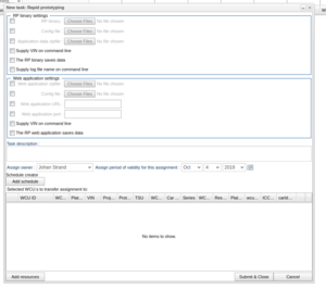
A Rapid prototyping (RP) task makes it possible to download RP binaries to multiple WCUs and keep track of the result files the RP task might produce. For more information about RP, see WICE RP How-To and WICE RP Manual.
The rapid prototyping tab can be seen in Figure "Rapid prototyping task".
An RP task must consist of at least an 'RP binary' or a 'Web application zip file'.
SoftHub
The SoftHub is a measurement system that can be run either as a stand alone unit or as a software module on the WCU, with functionality similar to the Signal Reader module. A SoftHub task is created much in the same way as a Signal Reader task.
When creating a SoftHub task, you select a .shub task file, and then proceed in the same way as the Signal Reader task.
The SoftHub task will generate result files. It may be interesting to know if certain signals reach certain values in these result files, therefore it is possible to add server triggers to the task that will trigger and add a suitable label to the corresponding result file. Read more about this here.
Signal Reader
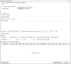
Signal Reader is a data capture module that allows monitoring and logging of CAN and FlexRay signals, as well as diagnostics data, and ECU-internal signals read by CCP or XCP. To create a Signal Reader task you proceed as follows:
1. You either select an assignment file of .haf format, or choose an assignment created in the assignment creator (see Signal Reader Assignment Wizard). Your current choice will be displayed in the "Chosen file" field.
2. When you have selected an assignment and one or more WCUs, the CAN buses defined in the assignment and on the WCU will be mapped. If they can be automatically mapped a green check symbol will be displayed, otherwise a red cross will be displayed. Clicking the mapping button will open the mapper. In the pop-up window you will have to map the different buses to each other manually and then save. Once this is done correctly, the red cross will become a green check mark, indicating that the mappings are ready to be automatically applied upon submit. Read more about this in I/O configurations and Mappings.
3. With a Signal Reader task you can monitor CAN, FlexRay, ODB-II and WCU-internal signals live by selecting "Monitor signals". When selected, two boxes will appear under the task description. In the left one you search for signals and drag them over to the right one where the signals to be monitored are listed. You can later see the monitored signals by pressing the Monitor Signals button either in the Tasks tab or in the Vehicles tab. It is also possible to copy the signals text in the bottom right corner of the right box. Next to the copy text button you can also paste signals as text where the pasted signal names will be matched against the list of unselected signals
4. You can choose if you want the signals to have their data source names as a prefix (e.g. CAN1.EngineSpeed instead of EngineSpeed).
5. The Signal Reader task will generate result files. It may be interesting to know if certain signals reach certain values in these result files, therefore it is possible to add Server Triggers to the assignment that will trigger and add a suitable label to the corresponding result file. Read more about this here.
A Signal reader task can be scheduled in the same manner as described for the Canrecoder task.
The Signal Broker
Signal Reader can act as a Signal Broker for other software components. For instance, the audio and video modules relies on the Signal Broker API of Signal Reader for evaluating start and stop trigger expressions. Moreover, the Signal Broker gives programmatical access to signals for Rapid Prototyping tasks. Read more about this in WICE Signal Broker API.
Files containing references to sequence files
If the measurement file contains references to sequence files, you are also required to select these in order to run the task. The portal scans the .haf file for such entries and presents this to you, see illustration 4.2. Click the button for each sequence file reference to upload each sequence file needed. Some requests in the sequence file may be for reading DTCs, and in such cases you can select the option of also reading associated Snapshots or Extended data. An example of this can found in Figure "Sequence Files References in .haf File".
Here, the .haf file contained two references to sequence files. As no sequence files have yet been uploaded, the selection for reading snapshot or extended data is grayed out. In Figure "Sequence File with Functional Query" we have selected one such sequence file containing (functional) DTC requests. Here we have checked that we would like to read Extended data. It is also possible to select both Snapshots and Extended data.
WICE internal signals
In addition to CAN and FlexRay signals, a number of internal signals (i.e. internal to the WCU) are also available. The following WICE-internal signals are supported: WICE Internal Signals
SoH
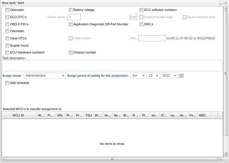
A State of Health (SoH) task collects specific status information from vehicles. You select which information you want the task to collect by filling in one or more of the checkboxes shown in Figure "SoH". The number of checkboxes shown can vary depending on the WICE installation. In order for SoH data to be correctly interpreted, relevant description files (e.g. SDDB) for the vehicles executing the SoH task may have to been available. To add such a description file for a vehicle, see The Edit Car Dialog.The six different options are:
- Mileage
- Voltage
- Read ECU software numbers
- Read ECU DTC:s (optionally including 'Snapshot' and 'Extended data')
- Read OBD-II PIDs
- App Diagnotstic Db Part Num
- DM1, Diagnostic Message using the j1939 protocol
- Odometer, reading the odometer using the j1939 protocol (available from WCU version 2.63)
- Clear DTCs.
- If reading DTCs is requested as well, those will be read before clearing the DTCs. (available from WCU version 2.63)
- If this option (Clear DTC) is chosen it is optionally possible to set a PIN code for unlocking a gateway module - e.g. Vehicle Gateway Module (VGM). (Available from WCU version 2.66)
- Engine hours, reading engine hours using the j1939 protocol (available from WCU version 2.64). The result for this can be read in the generated j1939-file from the task. It is a text type of file. In addition, a system value label called 'engine_hours' (as default, can be changed on a customer basis). This label shows the latest read value and is available on the vehicle.
This task can also be scheduled in the same manner as described for the Canrecoder task.
Some selections above might not be available to you as this is a configuration setting depending on customer.
SWDL
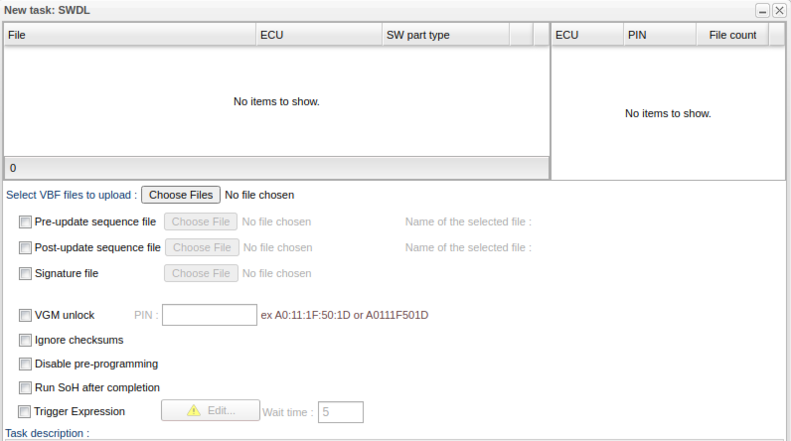
A Software Download (SWDL) task updates the ECU software in one or more ECUs in one or more vehicles. A number of Versatile Binary Format (VBF) files containing the ECU software need to be supplied, along with PIN codes to allow security access to re-program the ECUs. The PIN codes should be in the format of five hexadecimal numbers, e.g. ff:00:1a:2c:77 (or alternatively, omitting the colon separator, ff001a2c77). When a SWDL task has been created and assigned to one or more WCUs, it will cause all vbf files to be downloaded to the WCUs, and then the actual re-programming can be triggered by the vehicle user through the WCU status GUI web interface. The uploaded vbf-files are presented in a table along with its ECU and software part type (SW part type). In a separate table, the PIN codes for each ECU are presented along with the total number of files uploaded per WCU, see Figure "New SWDL task". To get an overview of how the files relate to the ECUs it is possible to choose the "Group by"-option when right clicking the ECU column in the file table.
SWDL tasks can optionally include a pre-update sequence file and/or a post-update sequence file. The diagnostic requests of those sequence files will be sent before and after the ECU re-programming respectively.
SWDL tasks can optionally include one signature file (containing checksums). The file is assumed to be a .xml-file. (Available from WCU version 2.66) If either of the optional files is selected, a field will appear to the right of the chosen file. This field will contain the name of the chosen file. (Available from WCU version 2.70)
SWDL tasks can optionally include a VGM unlock access control mechanism, with a PIN code for the VGM node. This is specifically for vehicles requiring this kind of access control for ECU re-programming.
By checking the box Run SoH after completion it is possible to let the SWDL task run the WCUs SoH task after the SWDL task is completed.
SWDL tasks can optionally contain a Trigger Expression which must be fulfilled within a specified time limit ("Wait time") for ECU re-programming to be allowed. The trigger expression follows the same syntax as Signal Reader trigger expressions (or Server Triggers, audio/video triggers), and should be built up from signals being measured in a Signal Reader assignment. The user must make sure that there is a Signal Reader assignment on the WCUs of the SWDL task, with the signals of the trigger expression being measured.
It is also possible to choose to ignore checksums and/or disable pre-programming using the corresponding checkboxes.
The SWDL module can be configured to perform SWDL either over CAN or over Ethernet (DoIP).
Video
A video task makes it possible to record and monitor live video from one or two cameras attached to a WCU. You can trigger recording of video in four ways:
- Trigger button: To initiate the recording you need to attach a button to the WCU in order to start in the video recording.
- Signal reader: Initiate the recording when a recorder in a Signal Reader assignment starts. The recording is started as soon as a Signal Reader recorder is started. You specify the name of the Signal Reader recorder (e.g. SREC_0) you want to start the video recording. You can also enter "auto" as the recorder name, in which case a recorder that include the Video_Device_n internal signal will be selected.
- Expression: Similar to the 'Signal reader' trigger option, the 'Expression' option lets the user specify start and stop trigger conditions based on logical expressions containing signals measured by the Signal Reader module. Note that the user must make sure the signals present in the expression are actually measured (otherwise the expression will never be true). Unlike the 'Signal Reader' trigger, there does not have to be a recorder configured in the Signal Reader measurement assignment. For an explanation of how to enter triggers, have a look here.
- None: start the recording as soon as possible. (Use this with caution, since it tends to produce prohibitively large video files.)
In addition to this, you can set the pre-trig time (not valid in the cases of the 'None' trigger option above). As an example, let's assume the trigger button method is selected. At the moment the trigger button is pressed the video has already been recorded for the number of seconds specified.
A maximum duration of the recording can also be set, in seconds from the start trigger event. If there is a stop trigger expression specified, the recording will be stopped either when the stop expression is fulfilled or the max duration is passed, whichever occurs first. If you do not enter a duration it will be set to a default value of 120 seconds.
If monitoring of video from a WCU is enabled, a live video stream will be transmitted which can be viewed using a RTP-based video tool, for instance Alkit Confero. This task can also be scheduled in the same manner as described for the Canrecoder task.
Read more about the video support in WICE here.
Applicable for all types
If enabled at your site, there might be an opportunity to announce to third party applications that a result file is available using a JMS API. By checking this box, as soon as a result file is added in the back-end this will be signaled using a customer specific event. The check box title is "Announce result file availability", this can be seen in the image in SoH.
Site specific features
Announce result file availability
If enabled at your site, there might be an opportunity to announce to third party applications that a result file is available using a JMS API. By checking this box, as soon as a result file is added in the back-end this will be signaled using a customer specific event. The check box title is "Announce result file availability", this can be seen in the image in SoH.
Retention time
This function works by setting a retention time in days which simply says that data coming in from the task, i.e. result files and positions will be kept the set number of days from when the data was collected. If, e.g. setting the retention time for an task to 30 days, will keep data until it is 30 days old where it will be automatically removed. See image.
It is possible to set a default retention time for resource groups. To do this, add a global value label named RETENTION_TIME to the resource group and give it an appropriate value. This value will then be used as a template value when creating a new task for this resource group. If multiple resource groups have this label and they have different values, the one with the lowest/shortest retention time value will be chosen as the template value.
