The Portal Administrator View
An administrator can do everything a user can do and more. In addition to the user, an administrator can create and modify users and stop assignments for any task. These new functions will be explained in the next 3 chapters. We will start with the search tab where two more buttons are visible. Next is the vehicles tab. Lastly is the administration tab with 5 sub tabs consisting of: the connect tab, the archives tab the GDS/SDDB files tab, the resource groups tab and the users tab.
The Search Tab
In addition to the functionality for an ordinary user, an administrator have one more button present. An administrator can send a stop command to any WCU. The new button can be seen in Illustration 32. Also, the administrator can search and view any user's task.
The Vehicles Tab
An administrator can do quite a many things in this view. Illustration 33 shows an example of this view. The table header along with the buttons “Edit Description” and “Get Log Files” are explained in the page for Vehicles.
At the bottom you have a set of buttons to aid in handling the WCUs. To add a new WCU to the portal, the “New” buttons opens up a dialog for that. The “Get Log Files” button fetches log files for the selected WCU from the portal.
The New WCU Dialog
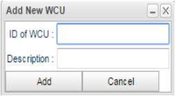
There are two ways that a WCU can enter the portal. The first is if you click the “New WCU” button and the second is the first time a WCU connects to the portal it registers itself. Ideally you will never have to add a WCU to the portal but just as a safety step you have the opportunity to add it yourself. When clicking the “New WCU” button the dialog in Illustration 34 opens up. You must enter the ID of the WCU as this is a unique identifier and you will be notified if the ID is already present on the portal. The description is optional but may be handy to remember which WCU it is.
Edit the WCU Configuration
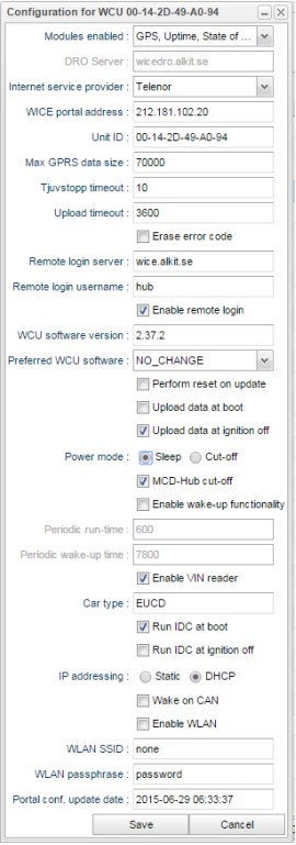
You can edit the configuration of the WCU from the portal. Simply click on Edit Configuration to open up the dialog in Illustration 35. Not all fields are editable but they are present as they convey information. The fields that are not editable are “WICE portal address”, “Unit ID”, “WCU software version” and “Portal conf. Update date” which conveys the date when the current version of the WCU configuration was set into play. Depending on the version of the WCU software not all configuration parameters will be available.
The set of check boxes for the different modules that are present is four and are at the top. Check or uncheck these to tell the WCU if they are present or not. Doing so will speed up the boot process. “DRO Server” sets which server to contact for DRO readouts. If “DRO” is checked, DRO readouts are allowed. “Internet service provider” can switch which SIM card to use. “WICE portal address” says which server to contact for fetching new assignments, configurations, upload data etc. “Max GPRS size” says what is the upper limit of how much data to send home over the GPRS link. If the data size is larger than the limit the WCU will wait until a local network connection can be established before the data will be transferred. The limit is set in kbytes. “Tjuvstopp timeout” tells the WCU how many seconds it should wait after the ignition is turned off before it tries to contact the WICE portal. “Upload timeout” is the maximum number of seconds the WCU should upload data before stopping. “Erase error code” will erase the car's error code the next time a DRO is made. “Remote login server” is the remote login server to use. “Enable remote login” must be turned on in order to remotely login to the WCU through the proxy above. As an increased security measure one can set´the user name to be used for authentication. “WCU software version” tells which version of the software that is currently running on the WCU. “Preferred WCU software” is the software that is to be installed on the WCU.
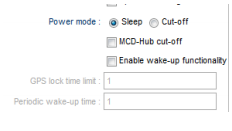
“Perform reset on update” removes all data on the WCU when installing a new WCU software. The two “Upload data at boot” and “Upload data at ignition off” tells the WCU when it should try to upload data to the portal. One of these should be set, if not, data will never be uploaded to the portal. “Power mode” has two settings, Sleep and cut-off. In cut-off, as indicated above, the MCD-Hub is not powered up on boot, nor is the WCU woken up at regular intervals to report battery voltage, GPS position etc. In the other mode, sleep, some more settings are visible as shown in Illustration 36 above. You can once again select the MCD-Hub to remain unpowered. In addition, you may enable the WCUs wake-up functionality. This function is simply made up of a cycle time called “Periodic wake-up time” and the corresponding “Periodic run-time” which indicates for how long I should be awake before going to sleep. The committo platform has some limits on the two settings and those are: minimum time to set between wake-ups is 10 minutes and the maximum time is 12 hours.
Lastly is “Enable VIN reader”. By unchecking this the VIN reader is not run on boot. As a short-cut you see which car type the WCU is currently connected to. If you click the entry you can edit that cars configuration through the dialog that opens which can be found in #The Edit Car Dialog, Next is the options at which time to run the IDC module. It can be done at boot or at ignition off or both or none. Remember though that not selecting any of these will make the IDC never to run. In SPA type of cars you must select how the IP addressing is done. If you select “static” you must also set which IP address the WCU should use. The “Wake on CAN” option means what it says, should the WCU wake up if it senses any traffic on the CAN interface. The last three options deals with WLAN. These are, for now, only useable on the MX4 type of WCU which has a WLAN interface.
The Edit Car Dialog
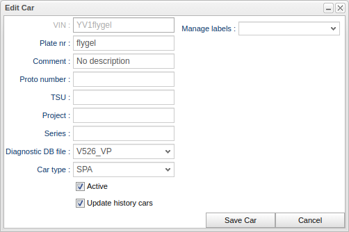
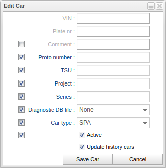
To edit the information about a car, press the “Edit Car” button. The dialog in Illustration 37 opens up. The entry you can not edit is the VIN entry. If you need to edit that you must instead create a new car. In order for the portal to be able to translate error codes into a human readable format, you must choose a diagnostic DB file to be used. It is important to select the correct one as the diagnostic error codes read out might be translated incorrectly or more probable, not at all. It is also important to select the right type of car using “Car type”. This controls the number of CAN buses and speeds and the number of Ethernet networks, if any, in the car. The “Active” check box controls whether the car should show up in tables and searches in general concerning cars. A car can never be removed as it has probably been involved in measurements but to recall an inactivated car you must actively select to view inactivated cars.
It is possible to update several cars at once by selecting multiple cars and then press the “Edit Car” button. By doing this you can selectively make changes to attributes of all the selected cars at once. To do this, the dialog is extended as one can be seen in Illustration 38 below.
Upload a Car Import File
It is possible to import a file that describes a set of cars. It can consist of both new cars and cars already in the database but that might need to be updated with new information.
A car import file consists of a comma separated file where each line describes a car. The first line of the file must look as follows:
VIN,regNr,description,project,protoNumber,tsu,series
There are seven attributes currently. When uploading the file you have a choice of modifying existing cars on the portal. If you do not check this box and there are cars that already exists, the import will fail.
Resource Groups
As described above in Vehicles#Resource Groups, you can define a set of resource groups in order to easily handle large groups of resources collectively. An example is if you have 100 WCUs in such a resource group and you would like to edit the configuration for all WCUs. Instead of having to open the configuration for each individual WCU, you simply open the configuration for the resource group, do your edits and when you press save, the configuration will be saved to all WCUs in one go. The resource groups are created in another panel which will be described later.
To add resources to a resource group you start by selecting the resources you are interested to add to a resource group. Resources already added to a resource group will render the corresponding add button disabled.
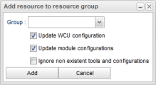
When you are satisfied with your selection you press either the button “Add WCU(s) to resource group” or “Add car(s) to resource group”. Pressing any of those buttons will show the dialog to the left. The group box will list the available groups. If you know the name of the resource group you can type the and as you type the box will show names that fit what you type.
The three check boxes requires a deeper discussion of what the mean. Assume you have a resource group that has been used for some time. A new WCU enters the portal and you would like to add that WCU to your group. A common situation is that you would like that WCU to be configured that same way as the rest of the WCUs in the resource group. This is accomplished by checking “Update WCU configuration”. If this requires an update of the WCUs software it will automatically be taken care of. Also, a WCU comes configured with a set of modules. Usually you will probably want to update the module configurations as well but in case you wish not to, simply uncheck that check box. There are also situations where there are no module configurations for some modules and if you press “Add” you will be prompted about that. If you for some reason do care about that you can check the “Ignore non existent tools and configurations” check box.
Modules for the WCU
A WCU can have a number of modules attached. This makes it possible to add new peripherals to the WCU for handling various tasks in acquiring measured data from a car. The six types of modules are:
- MCD-Hub
- Canrecorder
- GPS
- IDC (Internal Diagnostic Client)
- Uptime
- State of Health
- Signal Reader
- RFE (Road Friction Estimation)
To deal with each tool's configuration a new view is presented below. To open this view, press the button “Modules” as shown in Illustration 33 on #The Vehicles Tab. In the illustration above there are a set of tools present. Each type is grouped on the left side using a stack panel. Select the connected MCD-Hubs by selecting the MCD-Hub stack and select (click) the Canrecorder stack to see the canrecorders connected a so fourth.
Each tool has its own entry in each of the stacks. In Illustration 40 above there is only one MCD-Hub present and it is “0”. Each tool is recognized with a tool ID which is set by the WCU. This ID is usually not descriptive and therefore you have the possibility to set a name of your likings. Change the name by pressing the button “Edit name”. You can also add a description to the tool that shows up as a “tool tip” when hovering over the name of the selected tool. Analogously, change the description by pressing the button “Edit tool description”. To reload the set of available tools for both MCD-Hub and Canrecorder, press the “Reload tools” button.
Configure the MCD-Hub Module
The configuration for the MCD-Hub has only two settings. The first is the MCD-Hubs IP address and the second is the preferred firmware version. The other two configuration settings shown in Illustration 40 is “MCD-Hub firmware version” which shows the current version used by the hub and the second is “Last configuration update date” which states when the MCD-Hubs current configuration was brought into action. When you are done with your configuration you save it by pressing the “Save” button. If you for any reason need to reload the configuration, press the “Reload” button.
Configure the Canrecorder Module
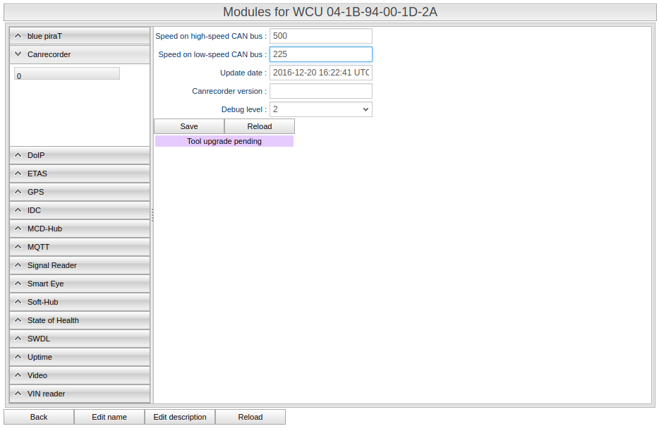
The configuration for the Canrecorder is shown in Illustration 41 below. There are four fields of which two are editable. In order for the canrecorder to work you need to set the high- and low speed CAN bus. The update date says when the last configuration was enabled and the canrecorder version says which version of the canrecorder software is used.
Configure the GPS Module
There are four settings involved:
- Enable GPS. Sets whether the GPS should be enabled or not. If you disable the GPS all the other settings will also be disabled.
- GPS sampling interval. Sets the position sampling interval in seconds.
- GPS monitor enabled. If this setting is enabled the WCU will continuously send its GPS position to the portal enabling real-time monitoring of the whereabouts of the WCU.
- GPS monitor interval. Set how often the position will be updated. The interval is in seconds.
Configure the IDC Module
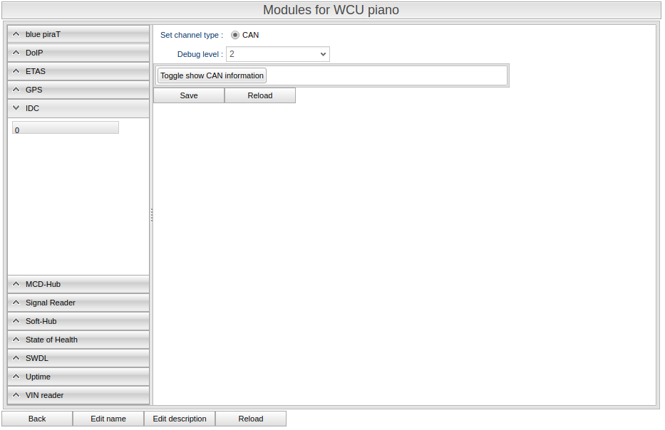
The IDC can be configured with which bus to communicate on given its assignment. You can actually even choose both where it will first try the Ethernet network (ETH), if it exists, and the CAN bus. If the car type in question does not have an Ethernet network, only the CAN option will appear.
Configure the Up-time Module
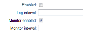
The module is used to report how much and how long the WCU is running. First of all you can enable/disable the functionality all together with the “Enabled” check box. Next is how often the up-time should be logged in seconds. The second check box, “Monitor enabled” is used when you would like the module to report its up-time in real-time and the interval for that, also in seconds.
Configure the State of Health Module
The state of health model has the same settings as the IDC module above.
Configure the Signal Reader Module
As of version 2.33 of the WCU software it is possible to monitor signals in real time. For this to happen you must enable the feature by checking the box “Enable monitor”. It is currently set at an update rate of once every second.
Configure the RFE Module
From version 2.35 of the portal there is a possibility to upload up to three files to configure the RFE module. The three files are:
- Configuration file
- Certificate file
- Binary file
The Administration Tab
This tab is a collection of the administrative tasks available in the portal. They are “connect car to WCU”, “Archives”, “GDS/SDDB file”, “Resource Groups” and “Users”.
Connect Car to WCU tab
To archive which car a specific WCU was in at the time an assignment was run can be done by connecting a car to a WCU in this tab. This is usually done automatically but in some situations it is necessary to do this manually
The area is divided into two tables, one for searching WCUs, the left one, and one for searching cars, the right one. When you start typing the name of the WCU you are looking for in the upper left corner just above the table, matching WCUs appear in the left table. To find the car you are looking, you do the same in the right table but here you have the option of using either the VIN or plate number.
To connect a WCU with a car you drag the WCU you would like to connect onto the car in the right table. When you drop it onto a car a small icon will show signifying that the WCU and car are connected.
To disconnect a WCU and car you simply press the icon for wither of the WCU or car. See Illustration 45 below for an example.
The connection is a sort of instantaneous carbon copy of the situation at the time that a task was created. If you later change the connection, already running/run tasks will not be affected.
The User Administration Tab
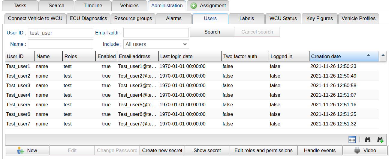
The basic layout of the areas is just the same here as before. At the top you have a search area, in the middle is a result are and at the bottom are a set of buttons. The tab with a set of example users is in Illustration 46 below. The eight columns are:
- User ID. The unique ID that the user must enter when logging in.
- Name. The name of the user.
- Roles. Depending on which roles the user has to, he/she have different privileges. The roles are non-overlapping, i.e. being an “Admin” does not necessarily mean that you can do everything a “User” can do.
- Enabled. Tells whether the account is enabled or not.
- Email Address. By registering an email address a user can receive notifications via email from a WCU when certain event occurs.
- Last login date. The date when the user last logged in.
- Two factor auth. Whether the two-factor authentication is turned on for a particular user.
- Logged in. You can see if the user is currently logged in.
At the bottom there are eight buttons. They are:
- The “New” button brings up the “New User” dialog which adds a new user to the portal
- The “Edit” button brings up the “Edit User” dialog
- The “Change Password” button brings up a dialog to change a user's password.
- The “Create new secret” button. Pressing this generates a new cryptographic salt to be used when generating one-time passwords. If you do this for a user without enabling the possibility to see the secret on the next login, renders the user unable to login to the portal. No dialog is opened, simply a message saying that a new one has been generated is shown.
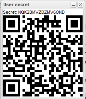
- The “Show secret” button. Shows a dialog with the cryptographic salt shown in clear text as well as the QR-code, more on this later.
- Edit roles and permissions
- The “Save headers” button. Saves the headers and their order to be used as default on later logins.
- Video. Start a video conversations with another user of the portal. You must have the software “Confero” installed for this to work.
The New User Dialog
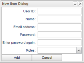
By pressing the “New User” button the dialog in Illustration 47 below appears. Mandatory fields are User ID and the two password fields. Remember that the User ID must be unique and you will be notified if it is not. Click the “Add” button to add the user or change you mind by clicking “Cancel”.
The Edit User Dialog
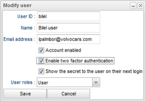
You can at any time modify a user by pressing the “Modify” button to bring up the dialog in Illustration 48 below. The User ID cannot be changed. A disabled account can not be used for logging onto the portal even if the correct user name and password are given. To modify the user roles, select or deselect a role by using the check boxes. To turn on two-factor authentication for a user, check the appropriate box. When you are satisfied with your modifications, press the “Save” button to make them permanent on the portal or press the “Cancel” button if you change your mind.
To enable two factor authentication, tick the check box “Enable two factor authentication”. This will force the user to add another special one time password in addition to the account password when logging into the portal. The one time password is generated by a program on either your computer or if you want to you can install it on your smart phone which is probably the best solution. The program that generates one time password is based on a cryptographic salt and the current time. The cryptographic salt is randomly generated by the portal and is individual for each user. A secret can at any time be regenerated for a user which will render the user unable to login if you do not tick the check box “Show the secret to the user on their next login”.
The Change Password Dialog
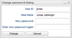
To change a user's password, press the “Change Password” button and the dialog in X Y will appear. It is pretty straight forward as you type in the new password in the “New password” entry and you need to confirm it by typing it again in the entry below it. If you are satisfied, click the “Change” button or the “Cancel” button if you decide not to change the password.
The Show Secret Window
A QR-code is shown that can be transferred to a smart phone by simply starting the authenticator app, point it at the screen and let the phone read the QR-code. An example of such a QR-code can be seen in Illustration 50. If the application that is to be used as a password generator do not support QR codes, the secret is shown in clear text at the top.
Edit roles and permission
In order to restrict access to resources and functions in the portal, there is a framework for controlling this using roles and permissions. Permissions are given on a set of resources. These permissions are grouped into roles, and roles are then attached to one or several users to be granted specific permissions.
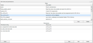
The “Edit roles and permission” dialog can be seen in Illustration 51. It consists of two tables. The top table holds the roles and the bottom one hold the selected role's.
You add a new role by pressing the button “New” and delete a role along with its permissions by pressing the button “Delete”. Role names must be unique. You can optionally add a description to the role. To edit a description for an already existing role, double click the entry you which to edit.
When you select a role in the top the table, the lower table shows that specific role's permissions. The permissions table consists of two columns, a string that is the actual permission and the set of resources that apply to that permission. In the illustration above there is only one resource but there can be list of resources that the permission applies to. Resource groups can also be selected as a resource. This means that the permission will be applied to those resources.
Each permission can be edited, deleted and you can create new permissions. When a permission is selected the buttons for editing and deleting permissions will be enabled.
Creating a new permission
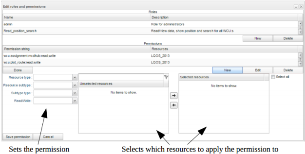
To create a new permission press the “New” button. It opens the following interaction depicted below.
A permission consists of five parts:
- The resource type. Which resource type should the permission apply to. Currently there are two resource types, WCU and Car.
- Resource subtype. Which subtype does the permission apply to. The set of subtypes currently is:
- View. This permission applies to the Vehicles tab. It has to do with whether you are allowed to list any WCUs in the table. Selecting this subtype makes the subtype type part unnecessary and therefore, it is removed if you choose this resource type.
- Conf. The permission says if you are allowed to work with a WCU's configuration.
- Module. The permission controls the access to individual module configurations. An example of a module is MCD-Hub.
- Assignment. Controls if a user is permitted to create/see assignments of a specific kind on a WCU.
- Plot route. To see a historic GPS track of a WCU a user must have this permission.
- Position. Allows a user to see a WCU's current position.
- Monitor. An assignment can have a monitor function to report data in real time. In order to see the real time data the user must have this permission.
- Subtype type. The above subtypes module, assignment and monitor uses this part of the permission as well. The reason is that these permissions is applied to the modules individually. In essence, you can have a permission to create IDC assignments but not MCD-Hub assignments as an example. Not all modules have assignments as well, and therefore, assignment and monitor types only has a subset of all modules. There is one last option, the All option. That option implies that the permission applies to all current and future subtype types.
- Read/Write. As the name tells it is a read/write control of the permission. As an example for a permission saying “wcu:assignment:mcdhub:write” means that a user is allowed to write assignments, i.e. create new assignments of MCD-Hub type. If this permission instead ends with read, it means the use can view such assignments, typically this applies to what is listed in the Search tab.
Selection of actual resources to apply the permission to
The last part of a permission is to select to which resources it will apply. The selection is made using the two tables you see in Illustration 52. To select a resource, which can be a resource group, you enter the name of the resource in the left table filter area. As you type, the table is automatically filled with resources matching the criteria. If a resource is part of a resource group the icon to the left is shown. If you hold the mouse over the resource name you will see which resource group it is part of. If you instead see the icon shown to the left, the resource is a resource group. Holding the mouse over the entry will show you which resources are part of the resource group.
To select a resource, drag it over to the right table or select the resource and then press the right-arrow. To deselect a resource, drag it to the left table or press the left-arrow.
There is a “Select all” option. It selects all current and future resources to which this permission should be applied.
When you are done, press the button “Save permission”. If you change your mind, press “Cancel” instead.
Edit a permission
To edit an already existing permission, select the permission and then press the “Edit” button. This will open an interaction similar to when creating a new permission, however, with the two topmost parts locked for editing, i.e. the selections resource type and resource subtype disabled.
When you are done editing press “Save permission” to save the changes or press “Cancel” to undo.
The GDS/SDDB File Tab
In order for the portal to be able to translate error codes into a human readable format, a GDS or SDDB file must be selected for a vehicle. The set of GDS/SDDB files to choose from is administered in this tab, see Illustration 53 below.
To upload a new GDS/SDDB file, press upload new file and you will be presented with dialog where you select the file, sets an optional name (if no name is entered, the file name is used) and an optional comment. To upload a new file for an existing entry, press the edit file button and you will be presented with a dialog where you can upload a new file. To edit the comment or the name that should show up when select which GDS/SDDB file to use for a vehicle, simply double click the cell and edit directly in the table.
The Resource Groups Tab
This tab is used to administer some parts of the creation and destruction of resource groups and more. The panel for administering the resource groups is depicted in Illustration 54, below.
At the top is a search field to search for resource groups. Next are two tables, side by side. The left table lists the resource groups found depending on your search criteria. When a resource group is selected, the resources that are part of the resource group are shown in the right table. Next, the functionality of the buttons will be covered.
Add and Remove Resource Groups
To add a resource group you simply press the “New resource group” button and the following window will show. Type the name for the new resource and press “Create”. If you change your mind, press the “Cancel” button. Resource groups are global and writable and that means that names must be unique. The reason for this is that a resource group name takes on the form as both the resources car and WCU and those must be unique and therefore the resource groups must also be unique. One can, however, imagine situations where this must not be enforced but at the moment this is the case.
To remove a resource group, press the “Remove resource group” button. Be aware that no warning is given if there are resources in the group when removing it.
Manipulating Resources in a Resource Group
In the right hand table in Illustration 56 below, you see a set of resources for a resource group.
Here are both WCUs and cars part of the group. In addition to the type there is a column named “Synchronized”. That column only applies to WCUs. The use of this column is as follows. Assume you have a resource group consisting of 50 WCUs. Further, lets make a configuration change to that resource group. Depending on where the WCUs geographically are and how they are used the WCUs will be updated at different times. How do you you know when all WCUs are up to date in the resource group? You could check them individually in the “Vehicles” panel but that is not very elegant and time saving. Instead, just watch the “Synchronized” column for the WCUs. When a WCU is up to date with respect to the group configuration the column will read “true”. The value is updated each 30 seconds.
You can remove individual resources from a group by selecting the resource and then press the “Remove resource” button.
Yet another button remains and it is the button “Base Group on Resource”. When you add a WCU to a resource group in the “Vehicles” panel you have the option of not updating the WCU configuration to match the one of the resource group's, see Illustration 39 in #Resource Groups. Using this function it is possible to base the whole group on a WCU's configuration rather than the group's configuration.
The WCU Status Tab
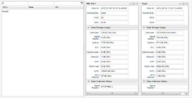
This view is supposed to be used as for supervising a set of vehicles. The supervision done in real time and the values for the set of vehicles are updated as soon as they arrive on the server from the different vehicles.
The set of status information collected comprises three parts:
General information:
- Alive, a heart beat signal
- Connectivity, what data rates are currently available to the vehicle.
- 3G
- 2G
- none
- Cell Signal Quality (CSQ). Indicates the signal strength of the mobile modem. The values are between 0 – 31, the higher the value the better. The special value of 99 is designated an unknown or not even detectable signal.
- GPS, simply a binary indicator of fix or no fix for the GPS.
Data Storage Usage:
This set of data informs how much collected data resides in the WCU for each type of data collector (module). Total data indicates how much of the total amount of data storage available is used. After that, each type of data collector is lined up.
Data Collection Status:
When modules collect data they go through a set of states when triggers starts, stops and other events occur. Currently, only such events for the signal reader module is available. An optional message accompanying the current state is shown in parenthesis.
The screen is divided in two parts, on the left hand side is a table with search functionality for finding the vehicles of interest and on the right hand side is the monitored vehicles. To monitor a vehicles you search for it in the table and then drag and drop the vehicle on the right hand panel.
A view of the panel is depicted in Illustration 57 below.


